

Key Takeaways
- Control your tool gap between 6% to 12% of the busbar thickness to achieve smooth cuts and beat competitors on final product quality.
- Follow the strict process for tool maintenance, which includes sharpening between 500-800m of use and ensuring the final installation parallelism error is below 0.01mm.
- Use the technical knowledge on tool gaps and cutting speeds to reduce costly rework and lower stress for the whole manufacturing team.
- Did you know that aluminum busbars cut best with a slightly *higher* speed than copper, but need a surface coating to avoid sticking to the cutting tool?
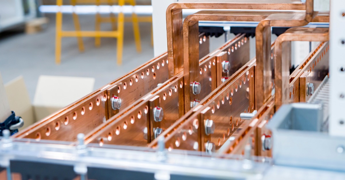
In the processing of copper and aluminum busbars, cutting is a fundamental step that determines the quality of subsequent assembly and conductivity.
A smooth cut not only reduces contact resistance during bolted connections and prevents localized overheating under high current conditions, but also reduces the risk of assembly interference and improves the overall reliability of electrical equipment. However, in actual processing, busbar cut sections often exhibit defects such as burrs, steps, and tilting. These problems mostly stem from improper equipment selection, unreasonable parameter settings, or non-standard operation and maintenance. Among mainstream busbar cutting machines, mechanical shearing machines are commonly used for processing medium and thick busbars due to their wide applicability and cost-effectiveness. To achieve high-precision, high-smoothness cut sections using this equipment, a comprehensive quality assurance system must be established, encompassing multiple dimensions such as equipment characteristics, process parameters, and tool management.
Choosing the Right Busbar Cutting Machine: A Core Prerequisite for Matching Busbar Material and Thickness
Busbar cutting machines rely on the relative movement of upper and lower cutters to separate the busbar. Their structural design and performance parameters directly determine the initial quality of the cut section; blindly selecting a machine can easily lead to section defects. This type of equipment is suitable for copper and aluminum busbars with thicknesses of 0.5-20mm, and it has a significant advantage in processing medium-thick busbars (8-20mm), achieving efficient cutting through stable mechanical force.
A high-quality busbar cutting machine should have a double-column guide structure, such as the SUNSHINE SS-50-3CNC busbar cutting machine from busbar processing machine manufacturer. This design ensures that the upper and lower cutters remain parallel during movement, effectively avoiding section tilting caused by unilateral force. Simultaneously, the equipment should support precise adjustment of the cutter gap, with an accuracy of ±0.01mm, to adapt to the processing needs of busbars of different thicknesses and materials. For example, a high-voltage switchgear manufacturer uses a CNC busbar cutting machine equipped with a servo motor-driven tool positioning system for 12mm thick T2 copper busbars. This system adjusts the tool trajectory in real time, resulting in a stable cut surface roughness below Ra0.8μm and a burr length controlled within 0.03mm, fully meeting the assembly requirements of high-voltage equipment.
It is particularly important to note that the busbar cutting machine must be matched to the tool type based on the busbar thickness. When cutting busbars thicker than 15mm, ordinary tools are prone to deformation due to excessive force, leading to steps or indentations in the cut surface. In this case, reinforced alloy steel tools must be used. These tools are made of chromium-molybdenum alloy, and after quenching, their hardness can reach HRC62 or higher, significantly improving their resistance to deformation and ensuring a smooth cut surface after cutting thick-walled busbars. For thin-walled busbars with a thickness of 0.5-5mm, lightweight high-speed steel tools can be used. These tools have a sharper cutting edge, reducing material extrusion deformation and preventing tearing and burrs on the cut surface.
Optimizing Mechanical Shearing Process Parameters: Precise Control of Key Variables in the Cutting Process
Even with a suitable busbar cutting machine, improper process parameter settings can still lead to cross-sectional defects. The core process parameters affecting the smoothness of the mechanical shearing cut cross-section include the tool gap and cutting speed. These need to be adjusted specifically according to the busbar material and thickness to ensure uniform stress and smooth fracture during the shearing process.
(I) Tool Gap: The Core Parameter for Controlling Burr Generation
The tool gap refers to the distance between the upper and lower cutting edges. Its size directly determines the stress distribution and fracture path during busbar shearing. Too small a gap will cause the busbar to be compressed and deformed, resulting in coarse tear burrs at the root of the cross-section; too large a gap will cause excessive stretching of the material, producing fine, long, entangled burrs.
When cutting copper busbars, because copper has moderate tensile strength (T2 copper has a tensile strength of approximately 220 MPa), the tool gap should be set to 8%-12% of the busbar thickness. For example, when cutting 6mm thick copper busbars, the gap needs to be controlled between 0.48-0.72mm. At this gap, the break lines of the upper and lower cutting edges can precisely align, resulting in a smooth, burr-free cross-section. If the gap is reduced to 0.3mm (only 5% of the thickness), the copper will tear due to excessive compression, and the burr length can reach over 0.15mm.
When cutting aluminum busbars, because aluminum has higher plasticity and lower tensile strength (pure aluminum’s tensile strength is approximately 110MPa), the tool gap needs to be appropriately reduced to 6%-10% of the thickness to prevent material collapse due to insufficient constraint. Taking a 4mm thick aluminum busbar as an example, the gap should be set at 0.24-0.4mm. If set to 0.48mm (12% thickness) according to the parameters for copper busbars, it will cause the aluminum to stretch and deform, resulting in burrs exceeding 0.2mm at the cross-section edge, and the hole wall flatness error will exceed 0.05mm.
(II) Cutting Speed: The Key to Balancing Efficiency and Quality
The cutting speed must be matched to the thickness and material properties of the busbar. Excessive speed leads to increased friction between the tool and material, raising the cross-sectional temperature and causing burrs to adhere. Insufficient speed reduces production efficiency and increases the risk of plastic deformation due to prolonged stress on the material.
For copper busbars, the cutting speed should be reduced by 0.5-1 m/min for every 1 mm increase in thickness. For example, the cutting speed for a 3 mm copper busbar can be set at 8-10 m/min. At this speed, the tool can quickly complete the shearing, reducing the contact time between the material and the tool and preventing overheating and adhesion. For a 10 mm copper busbar, due to the increased thickness, the speed needs to be reduced to 3-5 m/min to ensure the tool applies sufficient shearing force for a smooth break. Maintaining a speed of 8 m/min will cause the cross-sectional temperature to rise above 80°C, making it easy for copper to adhere to the tool edge, forming burrs larger than 0.1 mm.
The cutting speed for aluminum busbars needs to be slightly higher than that for copper busbars because aluminum has lower hardness and therefore less tool wear. For example, the cutting speed for 3mm aluminum busbars can be set to 9-11 m/min, while for 5mm aluminum busbars it can be reduced to 4-6 m/min. This ensures cutting efficiency while avoiding cross-sectional deformation caused by excessive speed. A new energy component manufacturer once set the cutting speed of 5mm aluminum busbars to 8 m/min, resulting in wavy lines on the cross-section and a flatness error of 0.08mm. After adjusting to 5 m/min, the flatness error of the cross-section was reduced to within 0.02mm, and the burr rate decreased from 12% to 3%.
Strengthening Mechanical Shearing Tool Maintenance: The Foundation for Extending Service Life and Ensuring Cross-Section Quality
Tools are the core components of busbar cutting machines, and their cutting edge condition directly determines the smoothness of the cut cross-section. Tool wear, chipping, or installation deviations can all lead to defects such as burrs and steps on the cross-section. A comprehensive tool maintenance system must be established to ensure that the tools are always in optimal working condition.
1.Tool Selection: Matching Material Characteristics is a Prerequisite
When cutting copper busbars, high-speed steel (HSS) or cemented carbide (WC-Co) tools should be selected. High-speed steel tools have a hardness of HRC60-65, strong wear resistance, and can withstand the high shearing force of copper, making them suitable for processing copper busbars with a thickness of 0.5-10mm. Cemented carbide tools contain 8%-12% cobalt, have a hardness as high as HRC65-70, and stronger wear resistance, making them suitable for thick-walled copper busbars with a thickness of 10-20mm. Their service life is 2-3 times that of high-speed steel tools. An electrical equipment factory used ordinary carbon steel cutting tools to cut copper busbars. The cutting edge wore out within two hours, and the burr rate rose to 40%. After replacing them with carbide cutting tools, the cutting edge life was extended to 8 hours, and the burr rate dropped to below 5%.
When cutting aluminum busbars, aluminum is relatively soft and prone to tool sticking. Therefore, surface-coated tools, such as TiAlN (titanium aluminum nitride) coated tools, must be selected. The coating thickness is typically 3-5 μm, and the hardness can reach HRC75 or higher, reducing adhesion between the aluminum and the tool and lowering the probability of burr formation. Simultaneously, the coating improves the tool’s high-temperature resistance, preventing accelerated tool wear due to cutting heat. MAC CNC busbar machine using TiAlN coated tools extended tool life from 50,000 cuts to 120,000 cuts, reduced tool sticking by 90%, and stabilized the burr rate below 2%.
2. Regular Sharpening and Inspection: Key to Maintaining Tool Performance
When the machined generatrix length reaches 500-800m, sharpening is required. Sharpening must be performed using a dedicated tool grinder with an accuracy of ±0.005mm to ensure sharpness and smoothness of the cutting edge. During sharpening, the grinding wheel speed should be controlled between 1500-2000 rpm to avoid overheating and annealing of the cutting edge due to excessive speed, which reduces hardness.
After sharpening, rigorous inspection is necessary: Use a micrometer to check the tool thickness deviation, ensuring the thickness difference between the upper and lower tool sections does not exceed 0.02mm. Excessive deviation will lead to uneven force during shearing, resulting in stepped sections. Use an optical microscope to inspect the cutting edge for chipping. If the chipping depth exceeds 0.1mm, the tool must be scrapped to prevent the chipped area from scratching the generatrix surface and creating burrs during cutting. A switchgear manufacturer failed to promptly inspect sharpened cutting tools, resulting in the use of tools with 0.15mm chipping to cut copper busbars. This led to scratches exceeding 0.2mm on the cross-section, causing a rework rate of 18%. After replacing the tools with qualified ones, the rework rate dropped to 2%.
3. Standardized Installation: Avoiding Deviations Affecting Cross-Section Quality
During tool installation, the parallelism error between the upper and lower tools must not exceed 0.01mm, which can be corrected using a dial indicator. Before installation, the tool mounting base must be cleaned to remove oil and impurities to prevent tool tilting. After installation, the tool must be manually rotated to check for any jamming and ensure smooth tool movement. If the parallelism error between the upper and lower tools exceeds 0.01mm, excessive force on one side will occur during cutting, resulting in a cross-section tilt angle exceeding 0.5°, affecting subsequent assembly. A power equipment factory once had a problem with tool installation deviation, resulting in a parallelism error of 0.03mm. When cutting an 8mm copper busbar, the cross-section tilted by 0.8°, making it impossible to connect with other components. After recalibration, the cross-section tilt was reduced to within 0.1°, and the assembly qualification rate increased from 75% to 99%.
Frequently Asked Questions
Why is a smooth busbar cut section crucial for electrical equipment?
A smooth cut is fundamental because it directly affects electrical conductivity and assembly quality. A rough cut can create high contact resistance when parts are bolted, which causes unwanted localized overheating under high current. High-quality shearing prevents assembly interference and ensures the overall reliability of the final electrical product.
What are the main defects seen in busbar cutting and where do they come from?
Common defects in busbar cutting include burrs, steps, and tilting of the section. These flaws mostly stem from errors in the manufacturing process, such as choosing the wrong equipment, setting improper process parameters like gap or speed, or failing to perform standard tool maintenance.
How does the tool gap setting change between copper and aluminum busbars?
Tool gap, the space between the upper and lower cutters, must be set correctly to control burr generation. For copper busbars, the gap is set wider, around 8%–12% of the thickness, due to copper’s moderate strength. For softer aluminum busbars, the gap must be slightly reduced, typically 6%–10% of the thickness, to prevent the material from collapsing or stretching too much during the shear.
What is the risk of selecting a cutting speed that is too high or too low?
Setting the cutting speed incorrectly reduces both quality and efficiency. A speed that is too fast increases friction and heat, causing burrs to stick to the tool and the material. If the speed is too slow, it increases the risk of plastic deformation because the busbar is stressed for a longer time during the cut.
Why do thicker busbars require reinforced tools and slower cutting speeds?
Thicker busbars, especially those over 15mm, require much more force to cut. Ordinary tools are prone to deformation under this high pressure, leading to steps or indentations on the cut surface. The cutting speed must also be slower to give the tool enough time to apply the necessary shearing force for a stable, clean break.
What is the importance of a double-column guide structure in a busbar cutting machine?
A high-quality machine should have a double-column guide to maintain the parallelism of the upper and lower cutters. This design prevents unilateral force during the shearing action, effectively stopping the busbar section from tilting. This is key to achieving a consistently flat and precise cut.
When should cutting tools be sharpened, and why is the sharpening process so exact?
Tools must be sharpened when the machined length reaches 500–800 meters to maintain performance. Sharpening should be done using a specialized grinder with extreme precision (±0.005mm) because careless grinding can overheat the cutting edge and reduce its hardness, leading to rapid wear and a high burr rate.
Which type of tool should be used for aluminum busbars, and what is its specific advantage?
Aluminum busbars are soft and tend to stick to the cutting tool, causing wear and burrs. Therefore, specialty surface-coated tools, like those coated with TiAlN (titanium aluminum nitride), should be used. This hard coating minimizes adhesion between the soft aluminum and the tool’s edge, greatly reducing burr formation and extending the tool’s life.
What is the most important installation check for new cutting tools to prevent section errors?
Tool installation is finished only after checking and correcting the parallelism error between the upper and lower tools. This error should not exceed 0.01mm. Excessive deviation in parallelism causes uneven force across the busbar during the cut, which results in a severe section tilt that will complicate future assembly.
How does the target tool gap for copper relate to the material’s tensile strength?
The correct tool gap is designed to match the material’s strength to ensure a smooth fracture. Since T2 copper has a moderate tensile strength (about 220 MPa), the 8%–12% gap setting allows the cut lines to align perfectly. If the material were much weaker, a wider gap would cause too much stretching and long burrs.